Peak Voltage Detector Circuit

Peak voltage detector circuit
A detector circuit in which regeneration is produced by positive feedback from the output to the input circuit. From: Modern Dictionary of Electronics (Seventh Edition), 1999.
What is basic difference between peak detector and AC voltmeter?
Explanation: A conventional ac voltmeter is designed to measure rms value of the pure sine wave whereas, the peak value of the non-sinusoidal wave forms can be a peak detector. 5.
How can opamp be used to determine the peak of a waveform?
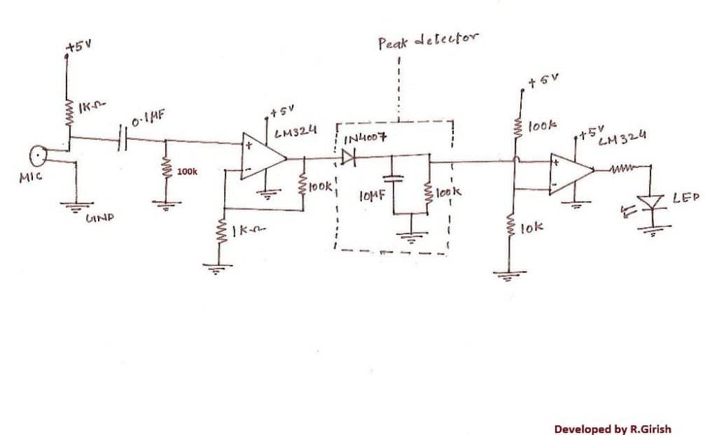
Op-amp based Peak Detector Circuit Whenever the applied input voltage signal is greater than the threshold voltage of the diode, the diode will get forward biased and acts as a closed switch. Here, the diode is connected in the feedback and hence the circuit works as a buffer circuit.
What is a peak detector circuit?
Definition: Peak detector circuits are used to determine the peak (maximum) value of an input signal. It stores the peak value of input voltages for infinite time duration until it comes to reset condition. The peak detector circuit utilizes its property of following the highest value of an input signal and storing it.
What is the function of peak detector?
Peak detectors capture the extreme of the voltage signal at its input. A positive peak detector captures the most positive point of the input signal and a negative peak detector captures the most negative point of the input signal.
What is the output of peak detector?
A peak detector is a series connection of a diode and a capacitor outputting a DC voltage equal to the peak value of the applied AC signal.
What is peak detector using op-amp?
Theory/Description: Op-amp based peak detector circuit is the modification of basic peak detector circuit, used to remove the voltage drop across the diode. Whenever the applied input voltage signal is greater than the threshold voltage of the diode, the diode will get forward biased and acts as a closed switch.
Why do we use AC Millivoltmeter?
millivoltmeter is useful at very high frequencies. It can be used for R.F. power measurement at frequencies of the order of gigahertz.
What is a zero crossing detector?
The zero crossing detector circuit changes the comparator's output state when the AC input crosses the zero reference voltage. This is done by setting the comparator inverting input to the zero reference voltage and applying the attenuated input to the noninverting input.
What is a comparator circuit?
A comparator circuit compares two voltages and outputs either a 1 (the voltage at the plus side) or a 0 (the voltage at the negative side) to indicate which is larger. Comparators are often used, for example, to check whether an input has reached some predetermined value.
What is S H circuit explain its operation?
1. The main function of a sample-and-hold (S/H) circuit is to take samples of its input signal and hold these samples in its output for some period of time. Typically, the samples are taken at uniform time intervals; thus, the sampling rate (or clock rate) of the circuit can be determined.
What is Clipper and clamper circuit?
Clipper Circuits are used to clip off a portion of wave from an input signal. Main element is diode and it is used in two ways series and parallel. Clamper Circuits clampa signal to different dc level. Along with diodes, capacitors and resistors are also used.
How does a clamping circuit work?
A clamper (or clamping circuit or clamp) is an electronic circuit that fixes either the positive or the negative peak excursions of a signal to a defined voltage by adding a variable positive or negative DC voltage to it.
How does a voltage doubler work?
A voltage doubler circuit outputs a DC voltage that is double the peak value of the AC input voltage, without using a transformer. There are many electrical design situations where an AC voltage signal is available (or can be created), but a larger DC voltage is needed for the circuit.
How do you calculate peak rectified voltage?
Rectified peak: VR=Vpp/2−2Vf.
Why is a peak detector also called the envelope detector?
The peak detector responds near-instantaneously to the peak value of the signal and discharges fairly rapidly. If the receiver dwells on a single frequency the peak detector output will follow the “envelope” of the signal, hence it is sometimes called an envelope detector.
What is positive clipper circuit?
A Clipper circuit in which the diode is connected in series to the input signal and biased with positive reference voltage Vr and that attenuates the positive portions of the waveform, is termed as Positive Series Clipper with positive Vr.
How will you realize a peak detector using a precision rectifier?
Peak detector When the input Vin exceeds Vc (voltage across capacitor), the diode is forward-biased and the circuit becomes a voltage follower. Consequently, the output voltage Vo follows Vin as long as Vin exceeds Vc.
How does a phase sensitive detector work?
A lock-in, or phase-sensitive, amplifier is simply a fancy AC voltmeter. Along with the input, one supplies it with a periodic reference signal. The amplifier then responds only to the portion of the input signal that occurs at the reference frequency with a fixed phase relationship.
What is half wave rectifier?
A halfwave rectifier is defined as a type of rectifier that allows only one-half cycle of an AC voltage waveform to pass while blocking the other half cycle.
15 Peak voltage detector circuit Images
AC Mains Voltage Detector Circuit Diagram Electronic circuit

underover voltage detector Detector Voltage regulator Audio amplifier

Low voltage detector Detector Circuit Electronics circuit

Noncontact AC voltage Detector using transistors and IC ElecCircuit

How to make AC voltage detector using the transistor BC547 Electronic

Pin on Circuits
Simple Peak Detector Circuit Hobby electronics Circuit Detector

LM339 based 4bit voltage indicator Electronic circuit design

Light Detector Circuit diagram Electronics Gadgets Electronics

This Circuit can compare the Light level in an area It uses a PN

Pin on

Noncontact ac voltage detector circuit using CD4060 Detector

OpAmp Integrator Circuit Circuit How to apply Capacitor

High Voltage Cable Detector HVDS High voltage Detector Cable
Post a Comment for "Peak Voltage Detector Circuit"